All categories
Featured selections
Trade Assurance
Buyer Central
Help Center
Get the app
Become a supplier
Công tắc assy
(Có 634 sản phẩm)
Alibaba
Phụ tùng & phụ kiện xe
Hệ thống điện xe hơi
Bộ ly hợp ô tô
Previous slide
Next slide
DFSK DFM Succe Trung Tâm bảng Điều Khiển Chuyển Đổi Assy 283002ZS00 + E705 với Một/C Chuyển
Ready to Ship
$30-35
Vận chuyển mỗi chiếc: $47.41
Đơn hàng tối thiểu: 10 pieces
Previous slide
Next slide
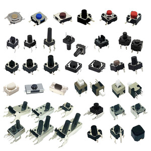
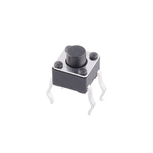
Mini tact chuyển 4.5*4.5*4.5H Đen nút 4P push button Tactile Thiết bị chuyển mạch tact vi chuyển đổi
Sẵn sàng vận chuyển
0,01 US$
Đơn hàng tối thiểu: 10 Cái
Previous slide
Next slide
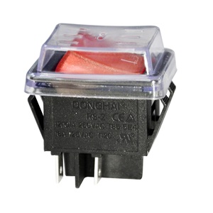
Donghai RS Hàn Lug nhựa kim loại IP67 2P 250VAC 20A Rocker chuyển đổi cho bàn đèn chuyển đổi hệ thống âm thanh
0,45 US$
Đơn hàng tối thiểu: 1000 Cái
Previous slide
Next slide
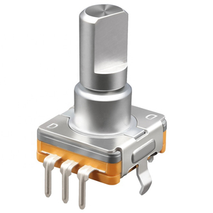
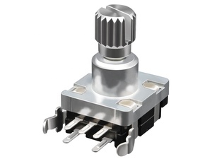
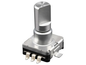
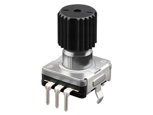
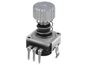
Bộ mã hóa quay ec11 Mini Rotary Encoder chuyển 11 Mét Chuột đẩy giá rẻ ec11 xoay Encoder chuyển Potentiometer nhà sản xuất
0,17-1,20 US$
Đơn hàng tối thiểu: 500 Cái
Previous slide
Next slide
Chất lượng cao chính xác CNC hợp kim nhôm tùy chỉnh CNC kim loại đẩy nút chuyển đổi các bộ phận nhôm gia công CNC
0,10-2,10 US$
Đơn hàng tối thiểu: 1 Cái
Previous slide
Next slide
84540-2403 50A130 845402403 50A130 Tự Động Trung Tính Bắt Đầu Chuyển Đổi
Assy
8-28 US$
Đơn hàng tối thiểu: 5 Cái
Previous slide
Next slide
Hot bán điện cửa sổ điện công tắc điều khiển 84820-0k011 Thạc sĩ chuyển đổi
Assy
cho Toyota Fortuner oem848200k011
9,60-10,50 US$
Đơn hàng tối thiểu: 1 Cái
Previous slide
Next slide
Chuyển Đổi Mới
Assy
84250 35070 Chỉ Đạo Wheel Nút Điều Khiển Cho Toyota FJ Cruiser 2012 2013 2014 2015 2016 2017
35-40 US$
Vận chuyển mỗi chiếc: 12,46 US$
Đơn hàng tối thiểu: 10 Cặp
1
2
3
4
5
More pages
16
Các danh mục hàng đầu
Phụ tùng ô tô hiệu suất cao
Hệ thống thân vỏ ô tô
Các bộ phận đa năng
Bánh, Lốp & Phụ kiện
Hệ thống điện xe hơi
Hệ thống chiếu sáng tự động
Hệ thống nội thất
Phụ tùng & phụ kiện xe máy
Phụ tùng & bộ phận đường biển
Động cơ xe hơi
Các thiết bị & phụ tùng tàu hỏa
Phụ tùng & phụ kiện đường ray
Phụ tùng & phụ kiện cho xe chạy bằng năng lượng mới
Hệ thống làm mát
Hệ thống truyền động ô tô
Phụ tùng & phụ kiện xe đua Go Kart & Kart Racer
Previous slide
Next slide
Các tìm kiếm liên quan:
công tắc Toyota lắp ráp
bộ phận công tắc tự động
bộ công tắc dành cho xe máy
chế độ công tắc xe hơi chất lượng cao
bộ chuyển mạch mitsubishi
bộ công tắc cửa sổ
cụm công tắc xe nâng
chuyển đổi assy trung lập bắt đầu
cụm công tắc áp suất dầu
khối công tắc kết hợp
công tắc mini joystick
mạch công tắc phanh
công tắc joystick
công tắc joystick điện
bật tắt linh kiện komatsu