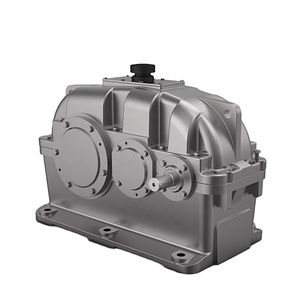
(4974 products available)
Mechanical gear reducers are the most important parameter for any mechanical structure because they help in reducing the input speed to the output speed by providing a good amount of torque. In the mechanical gear reducer, the type of reduction used is the toothed wheels in all the types.
Further classification of mechanical gear reducers is based on gears, namely:
, therefore, gear reducers: These reducers are the simplest types of reducers, where one gear is set inside the other, which acts efficiently and easily to reduce the speed and increase the torque by a double ratio. A Planetary gear consists of a central gear called a sun, and each set of gears around it called planets is attached to an orbiting ring. This construction gives a compact design with a high gear ratio. The bevel gear, which is conical, allows change of the shaft angles, generally at 90°but with a wide range of possibilities. These types are useful in the applications that demand change of direction of the drive.
Helical gear reducers: These are more efficient and quieter than the equivalent older generation of logger saws because of the nature of the teeth that are inclined.
Spur Gear: Commonly used in the traditional sense, these are old types of saws that are easily recognizable due to their teeth running parallel to the shaft axis.
Worm gear: These offer the highest reduction ratios of any other type because of the unique shape of a worm screw.
In order to work efficiently at a given speed, the electric motor used in most machines has to be geared down to reduce the speed and increase the torque, which is useful in many ways. The torque is the twist and speed is the revolution per minute. This is done using a gear reduction system. The basic working principle of gear reducers can be explained in a better way by considering the example of a simple hand drill. If one would hold the drill bit while it is attempting to drill, one would discover that it would turn it very easily, but while the speed could be high, the torque would have been lost. If the drill is placed on a soft surface and it is allowed to rotate, one will see that although the bit is spinning a lot faster, it does not have enough force to penetrate an object. Drills are designed with gear reduction systems that provide maximum torque to achieve drilling well.
Close fit: The gear reducer suits the motor in the application, which is coupled to by a close fit in size and performance.
Load: The maximum load in the application, static, and dynamic should be taken into account when choosing a gear reducer.
Speed: The entry speed to the gear reducer should be within the manufacturer's specified ranges.
Direction of rotation: Gear reducers are used to drive motors in both directions. Some can be driven in both ways. Almost all have preferential rotation. Check if the gear reducer is unidirectional, bidirectional, or omnidirectional.
Mounting position: Most gear reducers are mounted in more than one position. Some are positioned uniquely. Check that a gear reducer can be mounted in a specific position.
Duty cycle: The percentage of time a load runs at its maximum value in a duty cycle should be considered. A continuous duty cycle means that the maximum load is always used.
Environment: The gearbox reducers environment should be considered. Typical factors are temperature, humidity, dust, and water.
Reduction ratio: The required reduction ratio for gear reducers can be calculated from speed and torque requirements.
Efficiency: Gear reducer efficiency relates to how much input power is converted to output power, typically expressed as a percentage. High efficiency means less wasted power, but low efficiency does not as a margin.
Backlash: Backlash is the amount by which the teeth of a meshed pair of gears can be moved in either direction without effecting a drive. Some applications require a certain backlash. Others need a specific backlash.
Service: Ask how the gear reducer will be serviced. Stocked spares and easy repairs keep machines running.
Materials
The input shaft is generally made of alloy steel, which is used due to its strength and toughness, which are the required characteristics for an input shaft. Input housings are made of aluminum alloys. Input housing is light and does not rust. Spur gears are also made of alloy steel. Worm gears are bronze, which lacerages easily and wears down other material.
Maintenance & Repair
Reduction in life cycle and operating costs is possible through proactive maintenance strategies. Inspection and servicing schedules based on the hours of operation or the number of cycles can help identify and remove contaminants. Look for leaked seals.
Operational Knowledge
In order to ensure that gear boxes operate safely and effectively, it is important that operating personnel understand the responsibilities associated with operating machinery that incorporates gear reducers.
Product specification of mechanical gear reducer
Details such as the output, power, torque, speed, size, weight, input, and efficiency are typical specifications of mechanical gear reducers.
A1: A gear reducer, also called a gear reduction unit, is a tool that reduces the high speeds and low torque of electric motors to usable levels.
A2: Gear reducers are needed because electric motors drive bits and other industrial machinery that need to turn slowly and have lots of torque to work effectively.
A3: A gear reducer works by using different types of gears, like bevel, helical, and worm, to decrease speed and increase torque through mechanical advantage.
A4: The different types of gear reducers are planetary, spiral bevel, helical, spur, and worm gear types that offer varying speed reductions and torques.
A5: Industries that use gear reducers are manufacturing, agriculture, construction, power generation, aerospace, and robotics for torque and speed management.