All categories
Featured selections
Trade Assurance
Buyer Central
Help Center
Get the app
Become a supplier
0 5v cảm biến mức nhiên liệu nổi
(Có 139 sản phẩm)
2025-10-31
Alibaba
Dụng cụ & trang thiết bị kiểm nghiệm
Dụng cụ đo đạc & đo lường
Dụng cụ đo thăng bằng
Previous slide
Next slide
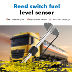
Cảm Biến Mức Phao Nhiên Liệu GLTV3 Với Báo Động Cao/Thấp Hoặc Cảm Biến Công Tắc Mức Nhiên Liệu
Ready to Ship
$52
Vận chuyển mỗi chiếc: $18.77
Đơn hàng tối thiểu: 1 piece
Previous slide
Next slide
Đồng Hồ Đo Mức Dầu Diesel GLTV3, Thiết Bị Đo Mức Kiểu Phao
677.017-893.662 ₫
Đơn hàng tối thiểu: 1 Cái
Previous slide
Next slide
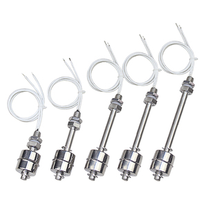
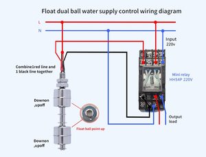
Mực nước chỉ số cảm biến Tank
Float
chuyển
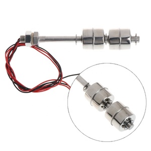
Float
mức Tank gắn Gauge cảm biến mức nhiên liệu
Sẵn sàng vận chuyển
108.323-135.404 ₫
Vận chuyển mỗi chiếc: 233.977 ₫
Đơn hàng tối thiểu: 1 Cái
Previous slide
Next slide
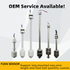
Không Có Công Tắc Cảm Biến Mức Nhiên Liệu Cảm Biến Điện Dung Cảm Biến Mực Nước Ống Công Tắc Phao Công Tắc Mực Nước Đầu Ra NPN
37.643-157.068 ₫
Đơn hàng tối thiểu: 100 Cái
Previous slide
Next slide
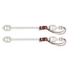
Float
loại kháng
0
-190 Ohm từ sậy chuyển đổi cảm biến mức nhiên liệu cho động cơ diesel và trạm xăng xe tăng dây
338.509 ₫
Đơn hàng tối thiểu: 10 Cái
Previous slide
Next slide
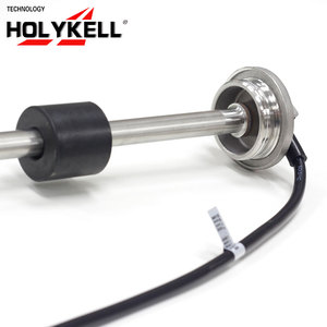
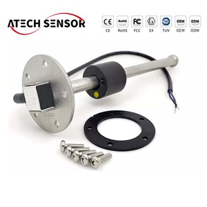
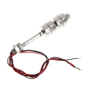
Bích Mounted kiểu
float
nước nhiên liệu mức độ tank Cảm Biến
812.420-1.624.839 ₫
Đơn hàng tối thiểu: 1 Cái
Previous slide
Next slide
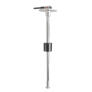
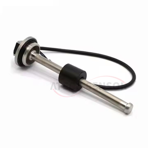
Holykell OEM Kiểu
Float
Cảm Biến Mức Nhiên Liệu Cho Mức Chất Lỏng Với Mặt Bích
1.083.226-3.791.291 ₫
Đơn hàng tối thiểu: 1 Cái
Previous slide
Next slide
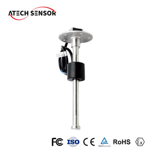
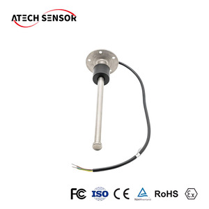
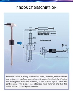
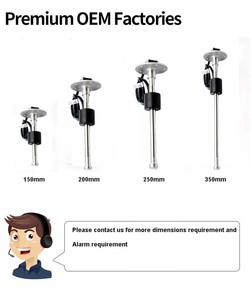
Cảm Biến Mức Nhiên Liệu Liên Tục ATECH
Float
541.613-2.708.065 ₫
Đơn hàng tối thiểu: 10 Cái
1
2
3
4
Các danh mục hàng đầu
Dụng cụ thử nghiệm và phân tích
Vật tư thí nghiệm
Dụng cụ đo đạc & đo lường
Thiết bị xét nghiệm
Previous slide
Next slide
Các tìm kiếm liên quan:
cảm biến mức nổi nhiên liệu
Cảm biến mức nhiên liệu điện dung 1000mm
cảm biến mức nhiên liệu hàng hải
Cảm biến mức nhiên liệu 4-20 mA
cảm biến mức nhiên liệu kiểu kháng nổi
cảm biến mức nhiên liệu A
cảm biến mức nhiên liệu kiểu phao
cảm biến mức nhiên liệu xe hơi
cảm biến mức nhiên liệu analog có thể cắt được
cảm biến mức nhiên liệu mô tô
cảm biến mức nhiên liệu diesel
cảm biến mức nhiên liệu cf moto
cảm biến mức nhiên liệu cách ly
cảm biến mức nhiên liệu rs232
cảm biến mức nhiên liệu ô tô


 Ready to Ship


 Sẵn sàng vận chuyển